

A 40-10 Meter DDRR Antenna – a Lesson for Hams and CBers – Vertical & Horizontal Polarity.
‘DDRR’ means “Directional Discontinuity Ring Radiator” antenna
See CQDX11.com for my other articles on CB DDRR Antennas HERE.
This article was one of a few that gave me the impetus to build and design my own DDRR! CB Radio DDRR HERE
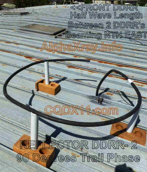
-1.1:1 SWR 56 Ohms impedance – 12 ” high – 104″ long Copper cable – 8″ gap & 8″ tap from upright along radiator. Its like a joke but it WORKS like a 9′ S/S Quarter Wave Whip!!
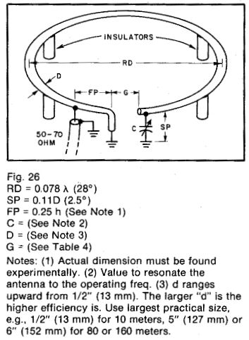 This antenna consists of a 1/ 4-wavelength element grounded at one end and wound into a single—turn coil. a few conductor diameters above the ground (see Fig. 26).
Shortly after the author‘s article on a practical DDRR Antenna appeared, a number of inquiries were received regarding low-frequency versions of this antenna for operation at ground level. After a little experimenting, the author came up with this version of a 40-meter DDRR which works quite well.
In early tests very fine QSOs were held with stations as far away as Phoenix, while the antenna was located inside the garage and surrounded by myriad metallic objects. When the antenna was relocated to the backyard, marked improvement was noted. even though this antenna site was marred by a sharp rise of l feet (1.22 m) in ground elevation, plus close proximity to house wiring and power lines. In spite of the ae obstacles solid oontset was easily achieved with stations up and down the West Coast, Encouraged by these results. we moved the antenna to a rooftop location which put it well in the clear insofar as metallic objects above the ground plane were concerned.
In this location. the DDRR really proved its worth.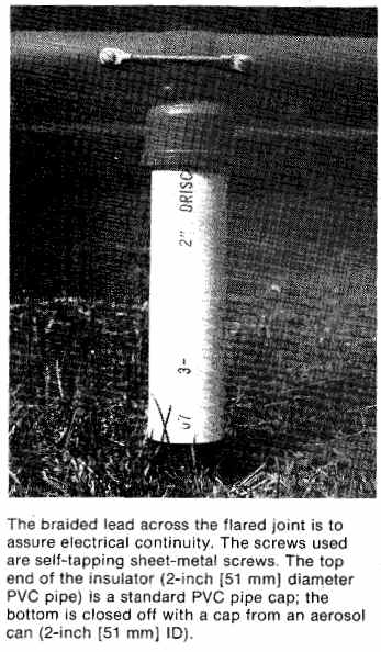
In spite of its low profile, a little over 1 foot (0.31 m), and its very small span, a_ few inches over 9feet (2.74 In), it was more than adequate when competing with any signal on the hand. The obvious conclusion from my experiments is that the 40-Meter DDRR is the apartment-dweller’s dream. It is principally for that group that this article is prepared. Other interested amateurs might be those who are limited, as this author is, by too much house on too little real estate; or those who for other reasons cannot cope with high towers, masts and guy wires.
Before this writers enthusiasm sends you out to rip down your inverted V or to dismantle your beam, remember this:
The DDRR, for all of its capabilities, will not supplant a full-size single~frequency antenna which is properly erected over clear terrain.
What it will do is provide an antenna which will enable communications of respectable quality, where heretofore it has been impossible because of inadequate space to erect a 40-meter antenna. Some consideration should also be given to the fact that the high-Q nature of the DDRR and its resultant narrow-band characteristics serve to reduce the noise level Boyer“ reports that in the initial experiments it was found that DX stations which could copy signals from either a vertical or a DDRR could only be heard on the DDRR due to the reduction in background noise.
So if you have a noisy location, it might be to your benefit to try the DDRR, regardless of what antenna you are presently using specifications. This was an obvious course since the material and the power bender were right at hand. The dimensions for 40 meters are: Ring — 9 foot (214 m) diameter. center to center. Height — l2 inches (0.3l In) from ground plant to element center. Gap g 6 inches (152 mm) from upright post center to open end of ring. In forming the ring to these dimensions, four 10-foot (3.05 m) lengths of tubing were used. A lO—degree bend was made at 9-inch (229 mm) intervals in three of the lengths.
The fourth length was similarly treated, except for the last 18 inches (0.46 m) which were bent at right angles to form the upright leg of the rings One end of each section was flared so that the sections could be coupled together by slipping the end of one into the flare of its mate. The required flares are easily made at the muffler shop with the aid of the forming tools. Another task which can best be completed at the shop is to weld a flange onto the end of the upright leg. This flange is to facilitate attaching the leg to the mounting plate which provides a chassis for the tuning mechanism and the coaxial— feed coupler.
After bending and flaring is complete, the ring is assembled and minor adjustments made to bring it into round and to the proper dimensions. This can best be done by drawing a circle on the floor with chalk and fitting the ring inside the circle. The circle must be slightly larger than the center-to-center diameter to that the reference line can be seen easily. For example, with two-inch (SI-mm) tubing the aaual diameter of the reference circle must be 9 feet, 2 inches (2.79 ml When youhave a satisfactory in between the tubing ring and the chalk ring. drill a l/kinch (6- mm) hole through each of the joints to accept a l/A~inch bolt. There bolts will clamp the sections together.
Also, they ran be used to attach the inauluton which support the ring at a fixed height above the groundplane. Making and Attaching the Insulators Insulators for the antenna were made from ll-inch (279—mm) lengths of 2-inch (51-min) PVC pipe inserted into astonde cap of the same material The PVC caps are first drilled through the center to accept the “4-inch (6-mm) bolt previously installed at the joints. The mps are then slipped cure the bolts and nuts are installed and tightened to secure the caps in place. The ll-inch length of pipe. when inserted into the cap and pressed firmly until it touches bottom. results in a total insulator length of [2 inches (0.3l in). Four insulators are required: one at each of the joints and one 56 Chime! 4Mlkln; the Mounting Plate The mounting plate is required to provide good mechanical and electrical connections for the grounded leg of the radiator, the coaxial feed-line connection, and the tuning mechanism. if you arousing aluminum tubing. you should use an aluminum piste, and for steel tubing, a steel plate to lessen corrosion irom the contacting oi dissimilar metals.Dimen- sions for the plate unshown in Fig. 27.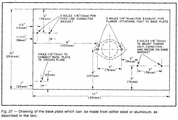
The important consideration here is that good, solid mechanical and electrical connections are made between the ground side at the coaxial connector, the ring base. and the tuning capacitor. The Turning Unit We found that the 9-foot (2.74 or) ring resonated easily with approximately 20 pF oi’ capacitance between the high end of the ring and the base plate or ground. A 35-pF double-spaced variable from thejunk box was pressed into service here (Cardweli NG-JS-DS). Any variable which will tune the system to resonance and which will not arc under full power should be satisfactory.
Remember, the ri‘ voltage at the high impedance end oi this antenna can reach 20 to 30 kV with high power. In if you are using the maximum legal limit, you would do well to consider using a vacuum variable capacitor. Since we limited our power to 500 watts PEP, the douthpaoed Card- well unit was satisfactory. To provide for full band coverage, the capacitor was coupled to a reversible, slow-speed motor which enabled the antenna to be remotely tuned from the operating position. An indicated SWR of M to l was easily achieved over the entire 40-meter band. The motored wusnwrpllll item made by Globe industries of Dayton. OH!
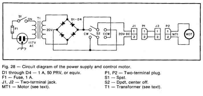
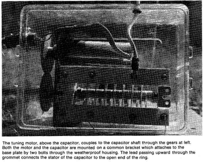
At 20 volts dc the shaft of this motor tutor at about i rpm which is idul for DDRR tuning. The gears used were surplus items if you cannot obtain gears. string and pulley drive will do almost as well. or you can mount both the motor and the capacitor inline and use direct coupling of course, if you operate on a fixed frequency or within a 40- to 50-er1 segment of the band, you can dispense with the motor entirely and simply tune the capacitor manually. In any case, the tuning Imit must be protected from the weather. We used a plastic refrigerator box to house the tuning capacitor and its drive motor. Fig. 28 shows the electrical connection for the motor. A small train transformer or power supply for toy slot-cars will work admirably as a tuning motor power source. Standard ac lip cord was used for the connection between the control unit and the motor.
Electrical Connections and the Groundplane
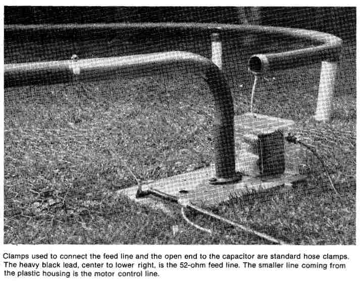
The connection between the open end oi the ring and the tuning capacitor is made with no. l2 wire or larger. On the end of the base plate appetite the tuning unit, and directly under the ring about 8 inches (203 mm) from the grounded post, install a bracket for a coaxial connector. The connector should be oriented so that the feed line will lead away from the ring at close to 90 degrees. Install a clamp on the ring directly above the coaxial connector. Connect a lead of no. llor larger wire from the coaxial connector- to the clamp. This wire must have a certain amount of flexibility to accommodate the movement necessary when adjusting the match. The matching point must be found by experimentation. it will be affected by the nature and quality of the ground plane over which the antenna is operating, The antenna will function over earth ground; however. in our location we found the electrical ground to be unpredictable.
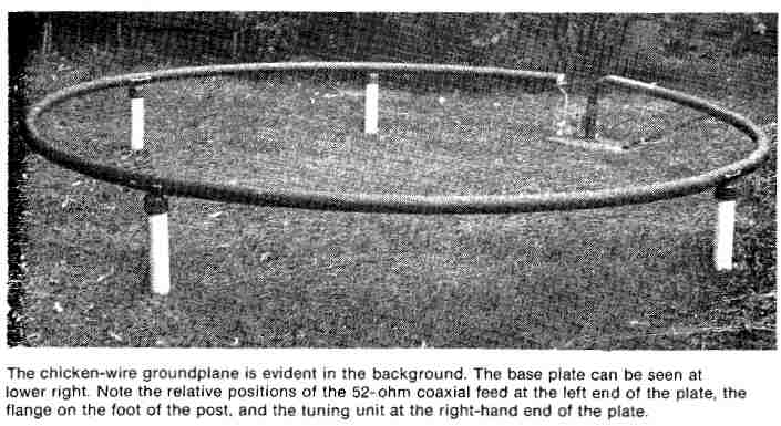
A ground plane surface of chicken wire (laid under the antenna and bonded to the base plate) provided a constant ground reference and improved performance. In a rooftop location sheet metal roofing should provide an excellent ground plane. A poor paint to nut. if it suits you. there is no reason why a final coat of enamel could not be applied.
Tuning Procedures
Once the mechanical construction it completed, the antenna should be erected in its intended operating location. Coupling to the station may be accomplished with either SZ-ohrn or 72-ohm coaxial cable. Tune and load the transmitter as with any antenna. While observing an SWR meter in the line, operate the tuning ground usually results in a matching point for the feed line for out along the m’rcumferenoe of the circle. in our installation a near-perfect match was obtained with the fad line connected to the ring about l2 inches (0.31 m) from the grounded post.
During testing, when the antenna was let up on a concrete sutfm without the ground plane, a match was found when the feed line was connected nearly 7 feet (2J3 In) from the post! As shown in photos, the compactness of the antenna is readily apparent. The ground plane it made up of three 12-foot (3.66-m) lengths of chicken wire, each 4 feet (l.22 In) wide. which are bonded along the edges It lhnut 64ml: (lSZ-mn’l) intervals. In our installation the antenna. with the ground plane, could be dismantled in about 30 minutes. lf portability is not important, it is heat to bond all of the joints in the tubing so that good electrical continuity is assured After all construction is completed. the antenna should be given a coat of primer motor.
Indication of resonance is the noticeable decrease in indicated reflected power. At this point, note the loading of the transmitter; it will probably increase markedly as antenna resonance is approached. Retune the transmitter and move the feed-point tap on the antenna for a further reduction in indicated reflected power. There is interaction between the movement at the feed tap and the mo- nanoe point; therefore, it will be necessary to operate the tuning motor uch time the up is adjusted until the lowest SWR is achieved.
Don’t settle for anything less than 1.] to I. With a good ground and proper tuning and matching, this ratio can he achieved and maintained over the entire band. Once the proper feed point has been loaned, the only adjustment necessary when changing frequency is retuning the antenna to resonance by means of the motor. If the antenna is to be fixed tuned, provide an insulated shaft extension of 18 inches (457 mm) or so to the tuning< capacitor shaft for manual adjustment. This not only prow‘des insulation from the high if voltage but also body- capacitance effects during the tuning process. Alternatlvu A number of materials other than the steel tubing used here are well suited for the ring element.
Standard E.M.T. or electrical conduit would work as well with a slight increase in weight. One advantage to be gained through the use of conduit is the elimination of the flaring operation since standard couplings would serve to connect each segment of the ring to its adjacent member. Another suitable material is copper tubing This material is superior to either exhaust pipe or conduit in terms of its conductivity characteristics. Another advantage of copper is that it is available in continuous lengths and the joints could be omitted entirely. The 2-inch (Sl mm) dimension is by no means mandatory.
Smaller diameter tubing has been used with satisfactory results.6 in fact, DDRR antennas have been fabricated with wire elements.
But, if the element diameter is reduced, the antenna times more sharply. Some experimenters may wish to go in the other direction and use a larger diameter. The author recommends the use of aluminum downspout with a diameter of about 4 inches (2 mm). This material does not lend itself to bending, however, and the ring must be configured as a regular polygon of eight or more sides. Because of the large number of joints involved, welding is about the only pnctitzl man: of joining the segments. Unless you are equipped to do this work yourself, the cost of welding might be prohibitive.
Anyone who undertakes to make a DDRR antenna of a large element diameter will be rewarded in terms of improved performance. Performance Results have been quite encouraging. and it is hoped that more and more hams will equip themselves with the DDRR in the future. The antenna has proved its worth and deserves more investigation by the amateur fraternity than it has been given in the past. No intensive efforts have been made to work Dx with the antenna described here: however. a low angle of radiation is conducive to DX. and this antenna demonstrates a low radiation angle.
It was found that distant areas, such as the East Coast, are more easily contacted than are stations nearby. All of the results could be attributed to peculiarities of individual stations or skip conditions, but since they are characteristics which can be anticipated with high-efficiency antennas having low radiation angle, we prefer that interpretation. Besides, where else will you find an antenna for 40 meters that is small enough to fit into a corner of the backyard and not protrude above the fence; or for that matter. which could be Miscellaneous Antenna Types ’1 mounted on the roof of an apartment ~- building or even a ranch-type house and not be visible from the street? Nearly everyone who listened to the description of this new antenna was enthusiastic.
The author hopes to hear many harm on the air working with the DDRR in the near future. This material was originally presented in QSTby W. B. English. W6WYQ.


