Discriminator output Decoding from Radio Frequency Scanners.The Discriminator output from a scanner is the raw, unfiltered signal that a scanner produces before it is sent to the audio stage for output through the speaker — also called the “baseband audio.” This discriminator source is required for applications such as Trunker, T4Win, UniTrunker, and DSD. Most scanners must have a simple modification made to them to feed the discriminator output to Data Slicers, or in the case of UniTrunker, a soundcard. Note that for providing a signal for ACARS decoding, a connection from an earphone or speaker output is all that’s required. This is because ACARS runs at a much lower speed, and the discriminator is not involved in AM reception. |
I have become interested in building the ULTIMATE CB RADIO so hence the research on this page.
This based on an existing CB Base Station I have already that works well on TX&RX.
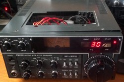 The ubiquitous Uniden PC-122 Yellow Dotted HYBRID Icom IC-701
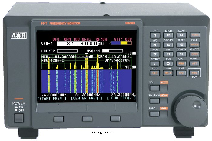
I want to add the latest means of actually viewing the RF and Audio on a computer screen LCD display similar to many latest Amateur radio transceivers similar to the ICOM IC-7300.
SEE MORE HERE on my ULTIMATE CB RADIO
How to modify your scanner or receiver with a discriminator output for FSK or PSK (e.g. POCSAG, FLEX, ERMES and AIS)
Why would you need a discriminator output?
Only a few scanners have a discriminator output as a standard feature. In most cases, you need to ‘operate’ on your scanner to make the discriminator signal available to the outside world. On this site, you can find pictures and descriptions of over 200 scanners, receivers, pagers and (marine) VHF transceivers that I modified with a discriminator tap.
Bill Cheeks contribution to the Radio Scanner Hobby below
Feb 02, 1999       SCANDATA.FAQ       02/02/1999

This article/file is for the benefit of all.

(c) 1999 (All Rights Reserved) by:
    Bill Cheek and -COMMtronics Engineering-

This file is for personal use only and may NOT be placed on
a CD-ROM nor any other media that conveys, stores, or
transports for any monetary cost including shipping &
handling, without expressed permission of the author. This
file can only be given away, absolutely free of charge, no
strings attached. If given away, it MUST be conveyed intact,
word-for-word with no editing, additions or deletions,
except as may be authorized in writing by the author.

                                   -Bill Cheek-
                                    Author

NOTE:  This Frequently-Asked-Questions (FAQ) file or article
       is one of a series of FAQs that I regularly publish.
       The complete list of FAQs is given below. If this one
       doesn't answer your questions, try one or more of the
       following additional FAQs:

1.  Scanner Modifications FAQ:  SCANMODS.FAQ
2.  Scanner Data Decoder FAQ:   SCANDATA.FAQ  <--- This FAQ
3.  Scanner Performance FAQ:    SCANPERF.FAQ
4.  Scanner S-Meter FAQ:        SCANSMTR.FAQ
5.  Scanner Radios FAQ:         SCANRADS.FAQ
6.  4-Level FSK Decoder FAQ:       4LFSK.FAQ
7.  Administrative FAQ:            ADMIN.FAQ

You can grab the latest of any of my FAQs directly from my
Web site as follows:
ourworld.compuserve.com/homepages/bcheek/faqs.htm
=============================================
Bill Cheek's Scanner Data Decoding
Frequently Asked Questions File
=============================================

Contents
=========

01: What is a 'Discriminator Output' and 'baseband audio'?
02: How can I find the Discriminator Output in my scanner?
03: How do I connect to the Discriminator Output?
04: How do I build or acquire a SIMPLE decoder interface?
05: How do I build or acquire a BETTER decoder interface?
06: So how do I decode digital data from the airwaves?
07: How can I decode CTCSS, DPL, and DTMF from the airwaves?
08: Is it possible to "TrunkTrack" without a TrunkTracker?
09: What if I don't want to build my own Data Decoder Interface?

Questions and Answers

==========================================================
01: What is a 'Discriminator Output' and 'baseband audio'?

There is a growing interest in tapping the baseband audio
out of various scanners for decoding of a variety of
esoteric signals, including CTCSS, SCA, FSK, RTTY, FAX,
Pager data, and trunked system control data, etc.

By and large, such signals cannot be taken from TAPE REC
jacks, headphone jacks, and EXT SPEAKER jacks because of the
voice-band filters that are between the signal source and
these output jacks.

Therefore, it is necessary to tap the wider "baseband audio"
directly at the output of the NFM discriminator chip in your
scanner. This is the first step to successful data decoding
from the airwaves.


===============================================================
02: How can I find the Discriminator Output in my scanner?

Table 1 shows a list of scanners, the discriminator chip(s)
used in the scanner, circuit symbols of those chips, and the
baseband audio (discriminator output) pin.

If your scanner isn't listed in Table 1, then refer to Table
2 to find its discriminator chip. The chips listed in Table
2 are all known Discriminators used in scanners and wide
coverage receivers.

Between Tables 1 and 2, you should be able to find the NFM
discriminator and its output pin for any reasonably modern
scanner.

Corrections and  additions to these lists are requested. See
my email and other addresses at the end of this file.

TABLE 1: SCANNER NFM DISCRIMINATOR CHIPS & PINS
Updated  01/28/99

                DISCR/DET        CKT     BASEBAND
SCANNER         CHIP TYPE       SYMBOL   AUDIO PIN
==============  ==============  =======  =========
unknown         MPS5071         n/a        9
AR-1000         TA-7787AF       IC-4       9
AR-2002         MC-3357P        IC-4       9
AR-2500		TA-7761P	IC-13      9
AR-3000         MC-3357P        ?          9
AR-800          MC-3361N        IC-200     9
AR-900          MC-3361N        IC-201     9
AR-950          MC-3361N        IC-201     9
AR-8000 NFM     TK10489M or-85M U1        11
AR-8000 WFM/AM  TA7792F         U3         8
BC-80XLT        MC3361B0        IC-101     9
BC-100XL        MC-3359P        IC-1      10
BC-100XLT       TK-10421M-2     IC-401    11
BC-140XLT       MC-3359P        IC-1      10 *
BC-200XLT       TK-10421M-2     IC-401    11
BC-205XLT       TK-10421M-2     IC-401    11
BC-235XLT       MC3361CDR2      IC-2       9
BC-250          ?               IC-3       9
BC-2500XLT      TK-10930VTL     IC-201    12-FM  13-AM
BC-3000 NFM/AM  TK-10930V       IC-202    12-NFM 13-AM
BC-3000 WFM     TK-10489M       IC-203    11
BC-350A         NJM-3359D-A     IC-3      10
BC-400XLT       NJM-3359D-A     IC-1      10
BC-560XLT       NJM-3359D-A     IC-1      10
BC-700A         NJM-3359D-A     IC-3      10
BC-760XLT       NJM-3359D-A     IC-2      10
BC-800XLT       MC-3359P        IC-1      10
BC-235XLT       MC3361CDR2      IC-2       9 *
BC-8500XLT      MC-3361BP       IC-9       9
BC-855XLT       TK-10421M-2     IC-401    11
BC-890XLT       NJM-3359D-A     IC-3      10
BC-895XLT       MC13371         IC-3       9 *
BC-950XLT       NJM-3359D-A     IC-2      10
BC-9000XLT      MC3361B0        IC-8       9
BC-9000XLT WFM  TK10489-MTL     IC-9      11
BC-9000XLT AM   LA1600A         IC7        8 or 9 (?)
BCT-7           MC3361BD        IC-2       9
HX-1000         TK-10420        U-201      9
ICF-SC1PC       TA3116FN        IC-401     9
ICF-SC1         TA3116FN        IC-401     9 *
Icom IC-2SRA    MC-3372          ?         9 *
Icom R-1 NFM	TK-10487  DET-A IC-1	  11
Icom R-1 WFM	TA-7787AF DET-B IC-1	   9
Icom R7100	Said to be "top of R230 on main PCB"  *
MR-8100         NJM-3359D-A     IC-3      10
MX-5000         MC-3357P        IC-4       9
MX-7000         MC-3357P        IC-4       9
PRO-2002        MC-3357P        IC-101     9
PRO-2003        MC-3357P        IC-104     9
PRO-2004 NFM/AM TK-10420        IC-2       9 (TP4)
PRO-2004 WFM    KB4419A         IC-1       6 (TP3)
PRO-2005 NFM/AM TK-10420        IC-2       9 (TP2)
PRO-2005 WFM    KA2243N/HA12413 IC-1      10 (TP1)
PRO-2006 NFM/AM TK-10420        IC-2       9 (TP2)
PRO-2006 WFM    KA2243N/HA12413 IC-1      10 (TP1)
PRO-2011        TK-10420        IC-1       9
PRO-2020        MC-3357P        IC-101     9
PRO-2021        TK-10420        IC-2       9
PRO-2022        MC-3361N        IC-1       9
PRO-2023        NJM-3359D-A       ?       10
PRO-2024        MC-3361N        IC-2       9
PRO-2025        NJM-3359D-A     IC-1      10
PRO-2026        NJM-3359D-A     IC-7      10
PRO-2027        MC-3361N        IC-2       9
PRO-2028        NJM-3359D-A     IC-2      10
PRO-2030        NJM-3359D-A     IC-3      10
PRO-2032	MC-3361         IC-2       9 (TP5)
PRO-2035 NFM/AM TK-10420        IC-2       9 (TP2)
PRO-2035 WFM    KA2243N/HA12413 IC-1      10 (TP1)
PRO-2040        MC3361BP        IC-2       9
PRO-2041        MC3361N         IC-301     9  *
PRO-2042 NFM/AM TK-10420        IC-2       9 (TP2)
PRO-2042 WFM    KA2243N/HA12413 IC-1      10 (TP1)
PRO-2050        MC3361CDR2      IC-2       9  *
PRO-23          MC-3361BD       IC-1       9
PRO-24          MC3361BP        IC-2       9 *
PRO-26 NFM/AM   TK-10930V       IC-14     12-NFM 13-AM
PRO-26 WFM      TK-10489M       IC-16     11
PRO-31          TK-10420        IC-1       9
PRO-32          TK-10420        IC-101     9
PRO-34          TK-10420        IC-101     9
PRO-35          TK-10421M-2     IC-401    11
PRO-36          TK-10420        IC-101     9
PRO-37          TK-10420        IC-101     9 (TP103)
PRO-38          MC-3359P        IC-1      10
PRO-39          MC-3361N        IC-201     9
PRO-41          MC-3359P        IC-1      10
PRO-42          MC-3361N        IC-2       9
PRO-43          TK-10427/-10420 IC-301     9
PRO-44          MC-3361N        IC-201     9
PRO-46          TK-10421M-3LT   IC-401    11
PRO-49          MC3361BP        IC-2       9
PRO-51          MC-3361BD       IC-1       9
PRO-60          ?               IC-301     9
PRO-62          KA3361          IC-301     9  *
PRO-64          MC3361N         IC-301     9
PRO-66          MC3361N         IC-2       9 (TP3) *
PRO-90          MC3361CDR2      IC-2       9
R-1600          NJM-3359D-A     IC-2      10
R-4030          TK-10421M-2     IC-401    11
SC1PC           TA3116FN        IC-401     9
SC1             TA3116FN        IC-401     9 *
SR-15           TK-10421D-2     IC-1       9
StandardCCR708A TK-10420D	Q602       9 *
TurboScan 2     3130-6056-502   U-201     10 or 16
WiNRADiO  NFM   MC-3372D        U2         9 TP20
WiNRADiO AM/WFM TA-7640AP       U5         9 TP29
WiNRADiO  SSB   LM324M          U6         1
Yaesu FRG-9600  MC-3357P        ?          9 *
=====================================================
* Not personally verified by me


     TABLE 2
DISCRIM     OUTPUT
CHIP         PIN
=========   ======
KA3361         9
MC13371        9
MC3357P        9
MC3359P       10
MC3361         9
MC3372D        9
MPS5071        9
NJM3359DA     10
TA3116FN       9
TA7640AP       9
TA7761P        9
TA7787AF       9
TA7792F        8
TK10420        9
TK10421D       9
TK10421M      11
TK10427        9
TK10485M      11
TK10487       11
TK10489M      11
TK10930V      12
CXA1111N      21 AM/WFM Only
HA12413        9 WFM Only
KA2243N        9 WFM Only
KB4419A        6 WFM Only

Once you locate the discriminator in your scanner, you have
to make its output conveniently available on the exterior
chassis, much like a headphone or tape recorder jack.

Figure 1 below shows how to determine the pin numbering
system for most integrated circuits.  Looking at the marking
side of the chip, there is either a notch or nook at one
end, and/or an embedded "dot" off to one side at one end.
The notch, nook, or dot signifies the end that starts with
Pin #1 and ends with whatever the highest numbered pin
happens to be.  Most IC's have 8, 14, 16, or 18 pins.

                  FIGURE 1
         TYPICAL NFM IC CHIP PINOUT
                                                NFM DISCR
          16 15 14 13 12 11 10  9    10uF/16v   Baseband
           |  |  |  |  |  |  |  |----+[|------> Audio Out
         +------------------------+
         |                        |   /-------> Ground
         |        TOP VIEW        |   |
  Notch  \          LABEL         |   |
         /  Dot     SIDE          |   ^
         | O                      | Scanner
         |                        |  Ground
         +------------------------+
           |  |  |  |  |  |  |  |
           1  2  3  4  5  6  7  8

NOTE: Figure 1 shows the baseband audio tap on Pin 9,
      though the pin number will vary from one chip
      to the next.


==============================================================
03:  How do I connect to the Discriminator Output?

HOOKUP PROCEDURE
================

If you need the raw NFM Discriminator baseband audio signal
for external purposes, the best way to access it is via a
jack installed in a convenient, unobtrusive location on the
scanner. Use Figure 1 as a general guide.

1A  BASE SCANNERS: Install an RCA or other jack in a desired
    place on the scanner's external case, typically the rear
    panel.

1B  HANDHELD SCANNERS: If you can find the space, use a
    standard monaural 1/8" phone jack or a 3/32" mini phone
    jack.  Some scanners are so cramped inside that even
    these won't fit. In that case a strip of 3 pinline
    sockets can be melted into the plastic case and wires
    soldered to the inside protrusions.

    The middle pinline socket is not connected to anything;
    it's just there as strength and support for the pinline
    plug you make, with the shield ground soldered to one
    end and the audio- center soldered to the other end:

    GND---o o o---NFM DSCR (audio)

    "Break-apart" pinline plugs/sockets are available from
    Mouser, DigiKey, and Hosfelt.

    Digi-Key:  p/n A208-ND          (800) 344-4539
    Hosfelt:   p/n 21-274           (800) 524-6464
    Mouser:    p/n 151-5520/5530    (800) 346-6873

    These little puppies are good for a lot of hacker needs,
    so get a supply!

2.  Connect the shell or outer frame part of the jack to
    scanner chassis ground.  (Use one end socket for pinline
    connections)

3.  Connect the (+) leg of a 10-uF tantalum capacitor (Radio
    Shack #272-1436) to the Discriminator output Pin. (Capacitor
    should be tantalum, but can vary in value from 2.2-uF to
    10-uF at a voltage rating of 16-35 vdc.)

4.  Connect the center conductor of a shielded coax (RG-174,
    etc) or shielded mic cable to the (-) leg of the
    capacitor. NOTE: if the distance from the NFM tap to the
    jack is less than 3", then a single unshielded hookup
    wire will do fine.

5.  Connect the shield of the cable at this end to a nearby
    PCB ground trace or spot.

6.  Connect the center conductor of the other end of this
    cable (or single hookup wire) to the center or hot lug
    of the jack.

7.  Connect the shield of the cable at that end to the
    ground lug of the jack.

8.  Fabricate or buy a shielded patch cable with one end to
    mate with the new jack on the rear of the scanner at
    that end....and the other end to mate with whatever jack
    is on the tape recorder, processor, decoder, or whatever
    device is to be connected at the other end.

Now you are ready to connect a data decoder interface to the
baseband audio output jack. See Figure 1 above.

=================================================================
04: How do I build or acquire a simple decoder interface circuit?

If you want to decode trunk control, MDT, some pager, fax and/or
other digital signals, you will need to build or buy a simple
2-Level FSK Interface to go between the NFM Discriminator/
Baseband Audio of the scanner and a standard PC serial port.

See Question #5 for a more sophisticated 4-Level FSK Interface.

   If you are not capable of building your own, or if you
   don't have the time to mess with it, I can supply either
   a Kit of all essential parts and detailed instructions,
   and you build it yourself, OR I can supply an  assembled/
   tested Decoder Interface, built inside a DB-25 shell and
   connector with a 3 ft shielded cable terminated with an
   RCA plug.  See Question #9 for details.

The DB-25 shell connects directly to a DB-25 comport on the
PC, or, if your comports are DB-9's, you can get a
DB25-to-DB9 adapter for it. You should, however, be able to
make your own following the below instructions.

This is a tried and true Data Interface circuit that's good
for everything we've tried, including a wide variety of
scanners. External power is not required.  This circuit
draws its power from the comport. It is similar to the
"Hamcom" and "data slicer" interfaces, but is optimized for
more scanners and more applications.

2-LEVEL DATA DECODER INTERFACE SCHEMATIC DIAGRAM
Copyright (c) 1998 Bill Cheek  <Revised 12/04/98>

               Note 4                               COM2
                                                  Computer
                                                 Serial Port
Scanner  |<------circuit----------------->|      DB25    DB9
                                                 ====    ===
Note                      o----o--|<--------o----->20 DTR  4
 5     Note 1             |    | 1N4148     |
NFM    10-uF         |\   |    o--|<--------|--o--> 4 RTS  7
 >-----+|[------o----|2 \ |    |            |  |
DSCR            |    |    \    o--+|[-->>>  |  |   Note 9
        100k    |    |LM  7 \     10-uF     |  |
 >--o--/\/\/----o    |741  6 >----------o---|--|--> 5 CTS  8
GND |                |      /           |   |  |
    o--/\/\/--o------|3  4/ Note 2      |   |  |
    |   3.3k  |      |  / |             |   |  |
    | Note 8  |      |/   |    Note 3   |   |  |
    |         o-----------|----/\/\/----o   |  |
    |                     |     100k        |  |
    |                     |                 |  |
    o---------------------|-----------------|--|--> 7 Gnd  5
    |                     |                 |  |
    |                     o-------->|-------o  | o-<2 TxD  3
    |            10-uF    |      1N4148        | |
    o-------------+|[-----o-------->|----------o |
    |                                            |
    |      Circuit                               |
    o--->>>Ground     o--------------------------o
    |                 |
 - -|- - - - - - - - -|- - - - - - - - - - - - - - - - - -
    |   o-------------o
    |   |
    |   |      Optional for TrunkFollower
    |   |      Control of a second scanner
    ^   ^       (See Note 10 and Q&A #8)
  Gnd  RxD
    COM3
  or other
  port for Trunk
  Follower control

 LEGEND:

     |
   --o-- = soldered connection/junction

    --o  = turn of the trace in the drawing
      |

   --|-- = crossover (no connection)
     +|[ = capacitor, polarized (note the +)
      >| = diode (anode->|-cathode)
      |< = diode (cathode-|<-anode)
 -/\/\/- = resistor
   -->>> = ground

 NOTES:
 1.  Use tantalum capacitors, +|[ polarity as shown

 2.  Radio Shack's LM-741 op-amp  works fine. Others might not!

 3.  Use 1/4 or 1/8 watt resistors to conserve space

 4.  Build circuit on a trimmed and fitted piece of perf
     board inside a DB-25 shell for max efficiency and space
     savings. DB-25 connects to PC's comport and a shielded
     cable from the scanner goes to the input; shield is
     ground and center is audio.

     Hi-res laser printed Instruction Sets available with precise
     schematics, drawings, perfboard layout, graphics, wiring,
     and solder points. Inquire:  [email protected]  or see:
ourworld.compuserve.com/homepages/bcheek/decode.htm
 5.  Many handheld scanners have no space to install a phone
     jack for the NFM Discriminator Output.  For such tight
     spaces a strip of 3 pinline sockets can be melted into
     the plastic case and wires soldered to the inside
     protrusions. The middle pinline socket is not connected
     to anything; it's just there as strength and support
     for the pinline plug you make, with the shield ground
     soldered to one end and the audio-center soldered to
     the other end:

     GND---o o o---NFM DSCR (audio)

 6.  For base scanners, install a female RCA jack on rear
     panel.

 7.  For handheld scanners where there is space, use a 3/32"
     mini or a 1/8" standard monaural phone plug.

 8.  3.3k is an optimized value for most scanners.  If the
     baseband audio output measures less than 0.350-V AC, with a
     voltmeter set to AC-volts at a 1v range, you should decrease
     the 3.3k resistor to 2.2k, or even 1k if if the measurement
     is under 0.250v AC.

     I measured 0.150v AC out of the baseband audio tap in a
     Sony ICF-SC1PC handheld scanner. The required resistor
     from U1 Pin 3 to ground worked out to 1k.

     The NFM baseband audio signal of most scanners should
     show 0.400v AC or higher, in which case the 3.3k resistor
     is just right.

 9.  Connect the interface to a comport on the PC.  Plug the
     input cable in to the scanner's NFM Discriminator
     Output Jack.  Tune to a desired signal and run the
     decoder software of your choice.

10.  If you are interested in using the "data decode"
     scanner to control or "TrunkFollow" a second scanner,
     then run a pair of wires off the Data Decoder Interface
     from unused TxD (Pin 2) and Ground (Pin 7) out the back
     of the circuit. This pair of wires will feed the RxD
     and Ground pins of another COMport on the PC.


=================================================================
05: How do I build or acquire a BETTER decoder interface?

First, understand that you may not need or want a "better"
decoder interface.  The 2-Level Data Decoder Interface given
just above is ample for most everything except "FLEX" and
ReFLEX" pager signals.  There may be other exceptions, but
they are few and far between.  In most cases, the simpler
2-Level FSK Data Decoder Interface will be all you need.

Secondly, understand that the more sophisticated 4-Level
FSK Data Decoder Interface cannot and does not replace the
simpler 2-Level version.  If you want the 4-Level interface,
that's fine, but you'll need the 2-Level, too.

   If you are not capable of building your own, or if you
   don't have the time to mess with it, I can supply either
   a Kit of all essential parts and detailed instructions,
   and you build it yourself,

   OR

   I can supply an  assembled/ tested 4-Level Data Decoder
   Interface, built inside a project box with a DB-9 output
   jack on one end and an RCA jack on the other end.  You
   will need to provide your own shielded cable terminated
   with an RCA plug on one end to mate to the box and
   whatever connector on the other end to connect to the NFM
   Discriminator Baseband Audio Output on your scanner.

   You will also need to provide a shielded straight-thru
   9-cond serial cable with a male DB9 plug on one end to
   mate to the 4LFSKDDI box and whatever connector on the
   other end to mate to the chosen PC serial port.

   You may also have to provide your own +/- dual polarity
   power supply. (Two 9v batteries can suffice.) See
   Question #9 for more details.

I'm not sure yet how to present the 4-Level FSK Data Decoder
Interface circuit as a plain ASCII schematic like shown above
for the simpler 2LFSKDDI circuit.  So for now, I have to refer
you to the Web Sites that support this circuit with graphics,
text, and/or software support.  You should research these sites:
geocities.com/SiliconValley/Horizon/6063/
http://www.qsl.net/pa3eik/4lev_fsk.htm
geocities.com/CapeCanaveral/Launchpad/4039/
geocities.com/CapeCanaveral/Launchpad/4039/PINFO.HTM
geocities.com/CapeCanaveral/Launchpad/4039/IINFO.HTM
geocities.com/CapeCanaveral/Launchpad/4039/POCFLEX.ZIP
geocities.com/ResearchTriangle/Lab/9339/
geocities.com/SiliconValley/Network/8916/4levelm.gif
I now have available a detailed Instruction Set on the
4LFSKDDI for those who find the above sites a little too
technical to handle. I can also provide Kits of essential
parts, less enclosure and power supply.  See Q&A #9.

==================================================================
06: So how do I decode digital data from the airwaves?

    First, you tap the Discriminator Output in your scanner.
    Then build the desired Data Decoder Interface and connect
    it to the Discriminator Output. Then connect the other
    side of the Decoder Interface to a com/serial port on your
    PC. Lastly, run the software that decodes the particular
    type of signal that you want to decode.

    In general, it takes different software for different
    kinds of signals, and I can't possibly cover them all
    here.  I will suggest that you start out with a free
    program called TRUNKER that decodes the control data of
    Motorola trunking systems.  This is one of the easiest
    to set up and get working; therefore, it makes a good
    test "platform" to prove up all your work before you
    venture into bigger and better things.  Motorola trunk
    systems are fairly common now.

    TRUNKER and a good set of documentation and limited
    support for it can be found at the following Web Sites:
http://www.geocities.com/CapeCanaveral/Lab/1060/beta.htm
or
web2.airmail.net/lblant1/dfw/digital.htm
    Apparently it is possible to decode certain kinds of data
    from the airwaves without a decoder interface - just
    software!  For info on decoding MDT signals with nothing
    more than a Windows PC and a sound card, check out:
geocities.com/ResearchTriangle/Facility/7646/
=============================================================
07: How can I decode CTCSS, DPL, and DTMF from the airwaves?

    That is strictly up to specialized hardware and/or
    software that kind of goes beyond the scope of this FAQ.
    Lots of software is out and about that will do it, and
    there are even possibilities for "roll your own"
    hardware decoders.

    But the first thing you'll need is the "baseband audio"
    output that is described in Questions/Answers #1-3
    above. The Data Decoder Interface described in Q/A #4 is
    good ONLY for trunking and pager types of data; not
    CTCSS, DPL, and DTMF, unfortunately.

    In fact, it takes specialized hardware and/or software
    to decode each of CTCSS, DPL, and DTMF; and each is as
    different as night and day.

    Some scanners come equipped for CTCSS decoding, but most
    do not. And none come equipped for DPL or DTMF that I
    know of.

    For more information about retrofitting CTCSS and DPL
    decoders to your scanner, contact:

       Communications Specialists, Inc.
       426 West Taft Avenue
       Orange, CA 92865-4296
       (800) 854-0547  Fax (800) 850-0547
       (714) 998-3021  Fax (714) 974-3420
       WEB:  http://www.com-spec.com/

    For a low-cost "roll-your-own" DTMF Decoder (hardware)
    there is a nice project done up in great detail in one
    of the back issues of the monthly WORLD SCANNER REPORT
    newsletter, V3N10. Backissues are always available at a
    nominal cost.  See:

    ftp://ftp.cts.com/pub/bcheek/products/prodinfo.zip

    There are other hardware and software solutions for
    decoding DTMF that I may include here later as I get the
    information verified and added.

    The WiNRADiO Digital Suite is awesomely capable of
    decoding CTCSS and DTMF.  See:  http://www.winradio.com

    For scanners in general, though, it all starts with a
    tap to the "baseband audio" point, so read over Q&A 1-3
    above for the details.


=============================================================
08: Is it possible to "TrunkTrack" without a TrunkTracker?

    It didn't used to be, but times do change and YES! It is
    now possible to track the trunks without a 'real'
    TrunkTracker Scanner, and better, for that matter!!!

    Like the other subjects in this FAQ, it all begins with
    a Data Decoder Interface. See Q&A #4 and Note 10 in that
    answer for the tiny extra addition you need to make to
    the Decoder Interface.

    Next, you need a PRO-2004, PRO-2005, or PRO-2006
    scanner, although we hope to add other scanners to the
    list in due time.  For now, it's one of those three.

      NOTE: It is possible to track the trunks with a
            AR-8000 and perhaps with one of the Opto
            Interfaces, but these are specialized situations
            where detailed info must be found elsewhere.

    Then you need a CE-232 Scanner/Computer Interface (or
    its predecessor, the HB-232). You will also need the
    hot, new Windows program for the CE/HB-232 called
    Pro-Turbo.

    Lastly, you need one fairly modern computer, Pentium 133
    or better, for the easiest way to track the trunks, but
    there is another way almost as easy, if you have two
    computers, one a 486DX2/66 or better and the other, a
    PC-386 or better.

    There are other requirements, too, but the above are the
    main ones.  It is beyond the scope of this FAQ to spell
    out all the details, but the V8N9 issue of the monthly
    World Scanner Report tells it all.  You can order this
    or any other back issue of the World Scanner Report
    since Jan-91, including 6-mo and 1-yr subscriptions.

    You can also download a more detailed text file on
    TrunkFollowing with the PRO-2004/5/6 from my FTP site at:

    ftp://ftp.cts.com/pub/bcheek/ce-232/trnkscan.txt

    For more information on the Pro-Turbo software for the
    HB/CE-232, contact:

    Paul E. Turton
    RR # 3; Wainfleet, Ontario Canada L0S 1V0
    E-mail:  [email protected]  or  [email protected]
    Web:     http://www.iaw.on.ca/~jabba/pro-turbo.htm

    For more information on the CE-232 Interface, you can
    download a file called PRODINFO.ZIP from:

    ftp://ftp.cts.com/pub/bcheek/products

    or you can view and download all the individual files
    from the \CE-232 directory.  Or, you can ask for it as
    an e-mail file attachment from:  [email protected]

    or see the information in my signature box below.

    But yes, it is now possible to track the trunks without
    a TrunkTracker scanner, and do it better than any of the
    "real" TrunkTracker scanners!  The cost can be a lot
    less than the cost of a real TrunkTracker, too. The cost
    largely depends on what you already have, or can
    scrounge up, but at worst, it's well within the budget
    of many scannists.


================================================================
09: What if I don't want to build my own Data Decoder Interface?

    See further below if you are intested in a 4-Level Data
    Decoder Interface.  First is info on the 2LFSKDDI:

    2LFSKDDI
    ========

    There isn't much of a technical obstacle to "rolling your
    own 2-Level Data Decoder Interface, but if lack of time,
    tools, or access to the parts is an obstacle, then you can
    acquire one in either of two ways:

    NOTE:  We can supply the 2LFSKDDI detailed Instruction Set
           alone for $5, ppd, USA and $7, ppd, foreign.

    1.  Kit of essential parts (you build it):  $15 + $8 S&H

        Includes:
        3 ea  Capacitor; tantalum; 10-uF/16v:
        1 ea  D-sub Plastic Hood/shell; DB25
        1 ea  DB25 connector; female; solder pin
        2 ea  Resistor; 100-k; 1/4-watt
        1 ea  Resistor; 3.3-k; 1/4-watt
        4 ea  Diode; silicon; 1N4148
        1 ea  Op-amp; LM741CN; 8-pin DIP
        1 ea  Perfboard; pre-cut, notched, trimmed to size
        1 ea  Shielded cable; 3-ft; w/RCA plug
        1 ea  Detailed printed instruction set, complete with
               graphics, photos, tables, and "what if's"...
        1 ea  3.5" floppy disk w/shareware & freeware decoder
               programs and utilities.

        Optional upgrade or add-on items:

     *  A. Shielded cable; 6-ft; w/RCA plug        + $2.00
     *  B. Shielded cable; 12-ft; w/RCA plug       + $4.00
        C. Port Adapter; DB25 male-to-DB9 female   + $7.50
           (adapts 25-pin Interface to 9-pin comport)

     *  Instead of the standard 3-ft cable w/RCA plug

-=OR=-

    2.  Assembled/tested 2-L Decoder Interface     $40 + $8 S&H

        Includes:
        1 ea  Data Decoder Interface built into a DB25 shell
               with standard 3-ft shielded cable w/RCA plug.
        1 ea  Detailed printed instruction set, complete with
               graphics, photos, tables, and "what if's"...
        1 ea  3.5" floppy disk w/shareware & freeware decoder
               programs and utilities.

        Optional upgrade or add-on items:

        A. Built with  6-ft shielded cable and RCA plug  + $2.00
        B. Built with 12-ft shielded cable and RCA plug  + $4.00
        C. Port Adapter; DB25 male-to-DB9 female         + $7.50
           (adapts 25-pin Interface to 9-pin comport)
        D. Custom enhancements/designs per your specs    +$10/up


    4LFSKDDI
    ========

    CAVEAT:  It may be illegal to decode certain 4LFSK signals.
             You must determine that for your self and cease
             interest in the subject if not legal in your area.

    If you are intested in a 4-Level FSK Data Decoder Interface
    we have a detailed Instruction Set ready to go, as well as a
    Kit of Essential parts, less enclosure and power supply.

    Assembled and Tested units are not ready yet, but.....I may
    have available some built/tested prototype units that have
    been proved fit for consumption.

    One or more of the following may be available:

    1.  Instruction Set Only - you build from it.
        8-pages of hi-res laser printed text, charts,
        photos, drawings, and detailed, hand-holding
        guidance:   Price: $5, ppd, USA;  $7, ppd, foreign

    2.  Kit of Essential Parts, plus detailed Instruction Set
        from (1) above, less enclosure and power supply. See my
        4LFSK.FAQ file for details, or the following web site:
ourworld.compuserve.com/homepages/bcheek/4lfsk.txt
        Price: $20 + $8 S&H, USA;  $20 + $15 S&H foreign

    3.  Kit of Essential Parts, incl power supply.    Price: TBA
    4.  Assembled/Tested 4LFSKDDI, less power supply. Price: TBA
    5.  Assembled/Tested 4LFSKDDI, incl power supply. Price: TBA


    TO ORDER:  Use e-mail, fax, or postal mail per the
               information in my signature box below. MC/VISA or
               M.O. preferred. Personal and company checks okay,
               but shipment delayed until bank clearance. No
               COD's and no shipments to PO Boxes or mail drops.
               Alaska, Hawaii and foreign shipping extra.

       TERMS:  All sales are final; no returns-no refunds. 30-day
               Performance Warranty on the Assembled/ Tested
               Decoder Interface is strictly limited to Motorola
               SmartNet trunked data signals using TRUNKER.EXE
               despite that it will work on many other kinds of
               data, too. We just can't support it all.  Repair
               or replacement at our option during that 30-day
               period. No warranty on Kits.

               Not responsible/liable for illegal use of this
               information and/or these products; nor for any
               consequences thereof. You must determine
               lawfulness of these products for your applications
               and region and not use them, if illegal.

               Use of this information and/or these products is
               100% exclusively at your own risk.

               You must determine suitability and fitness of
               purpose of these products to your needs.  I will
               not accept responsibility or liability for any
               damage or loss that results from use of these
               products, nor for damage or loss that results from
               connecting these devices to a scanner and/or a
               computer.

               You must determine all risks and accept all
               consequences of any damage to hardware and/or data
               stored in the computer.

============================================================
That's it for now.  I will keep this FAQ updated.  If you
see things that need to be added to it, by all means, let me
know. If this FAQ fails to address your question(s), then
hit me with 'em again, but be specific.  And be detailed
with symptoms and observations if you need tech support on
mods or troubleshooting and diagnosis.  Use e-mail.

Copyrighted (c) 1999 (All rights reserved) Revised 02/02/99

------------------------------------------------        --
Bill Cheek - President/CEO/Publisher            \      /
COMMtronics Engineering/World Scanner Report     \    /
Box 262478 ~ San Diego ~ CA ~ 92196-2478          \  /
Voice: 619-578-9247 (1:30-5:30pm, PST, weekdays    \/
  Fax: 619-578-9247 (any time)                     /\
                         /  \
ftp.cts.com/pub/bcheek                     /    \
ourworld.compuserve.com/homepages/bcheek /      \
------------------------------------------------        --

========================END OF FILE===========================

RIP BILL CHEEK - A true radio enthusiast and gentleman.